LINK to the PDF file of the blog-post.
An ultra high performance enclosure is the heart of the passive house concept. The enclosure should be airtight and highly insulated, with limited thermal bridging. Additionally, the enclosure should be designed to mitigate potential durability issues related to moisture. Design for moisture management is important at all construction types but becomes even more critical when wood frame construction is used due to the moisture sensitivity of wood-based building materials. In previous posts, I’ve addressed the context and design of the Orchards at Orenco and the construction of the building foundation.
In this post, I will describe the construction of the Orchards enclosure in more detail, while providing additional commentary on specific aspects of the design. The Orchards team worked closely during the design phase to identify the most optimal enclosure design, striving to achieve the best balance of performance, constructability and cost. A more in depth examination of several key project details, and a discussion of our collaborative process during design and construction, can be found in a paper delivered earlier this year at the BEST 4 Conference: Five Not So Easy Pieces – Designing and Building the Passive House Enclosure.
Construction of the Orchards enclosure was challenging in many ways, but the greatest challenge resided in the planning and coordination effort, given the atypical assembly designs and specifications and the relative complexity of the enclosure detailing. Heading into the construction phase, we were uncertain how tight we could get the building (58,000 square feet of floor area in three stories) so we planned a week of float into our schedule to allow for testing and remedial air sealing work, if necessary. After completing our enclosure coordination meetings and submittal process, we constructed a large exterior wall mockup on site and it was here that we worked out many of the loose ends of the detailing and finalized some small tweaks to the design details, prior to execution on the actual building.
We constructed a large exterior wall mockup on site and it was here that we worked out many of the loose ends of the detailing and finalized some small tweaks to the design details, prior to execution on the actual building.
The exterior walls are framed with 2×10 Douglas fir, sheathed on the exterior with 1/2″ plywood. To reduce thermal bridging at the walls as much as possible, we used advanced framing techniques such as 24″ stud spacing and optimized framing around rough openings.
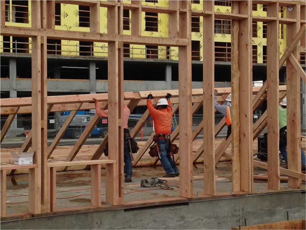
Raising the walls at Orchards. The exterior walls are framed with 2x10s, while interior walls are framed with 2x6s and 2x4s.
The plywood sheathing serves as the primary air barrier material at the exterior wall assembly. Once the majority of the wall framing was up, our crew moved around the building, taping all joints and seams in the sheathing with SIGA Wigluv, a specialty tape product manufactured in Switzerland and engineered specifically for air sealing. We typically used 4″ wide tape and 6″ tape at the inside and outside corners. At the outside corners, the plywood often butts together roughly; we were concerned about the void behind the tape, which could lead to tears or ruptures, so we placed a small foam backer rod in those corners before applying the tape. The Wigluv tape is vapor permeable, adheres extremely well to the plywood substrate and was excellent for the application. On previous projects where we’ve pursued a high level of airtightness, we’ve used a similar sealed sheathing approach; however, we’ve used wet-applied silicone sealant at gypsum sheathing joints and seams. Although the tape is quite expensive, the installation is much simpler and faster than the sealant method, thus labor costs are reduced significantly.
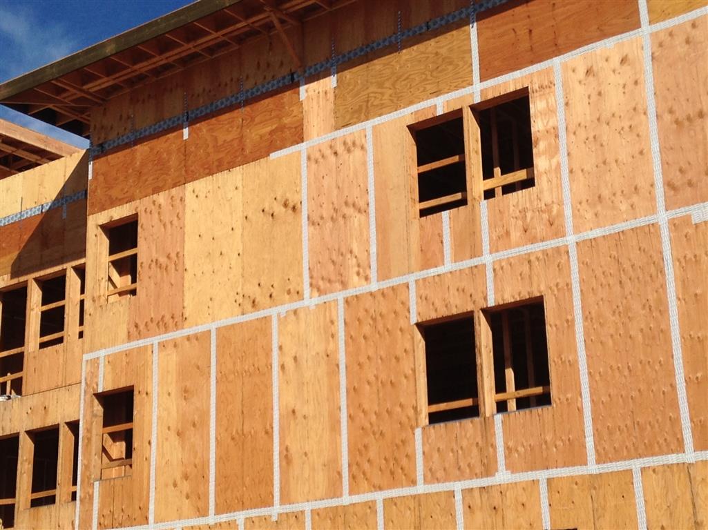
View of exterior walls prior to preparation of the window openings. The plywood sheathing serves as the primary air barrier material at the walls. All joints in the sheathing are sealed with Wigluv tape.
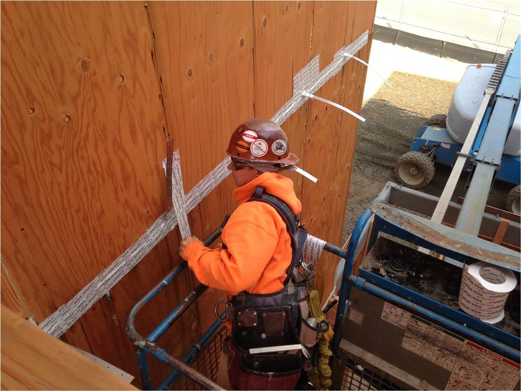
Tissi applies Wigluv air sealing tape at metal strap penetrations of the passive house enclosure.
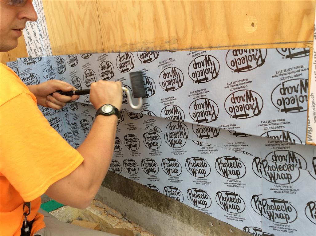
Doug installs self-adhered membrane (SAM) at the base of the wood frame walls, lapping onto and sealing to the concrete foundation. This membrane provides air barrier continuity from the foundation to the exterior walls. The membrane also serves as a secondary base of wall flashing to ensure no water migration into the moisture sensitive wood components of the wall. A laminate roller is used to apply pressure to the SAM to facilitate adhesion to the substrate and eliminate air pockets and pinhole leaks.
We used EuroLine 4700 Series ThermoPlus tilt-turn windows and doors, manufactured just outside of Vancouver, B.C. These windows feature tilt-turn operation and are triple-glazed, highly airtight and well-insulated, with a U-value of 0.14. The frame material is RAU-FIPRO – a fiberglass-vinyl hybrid developed by Rehau, a German polymers company.
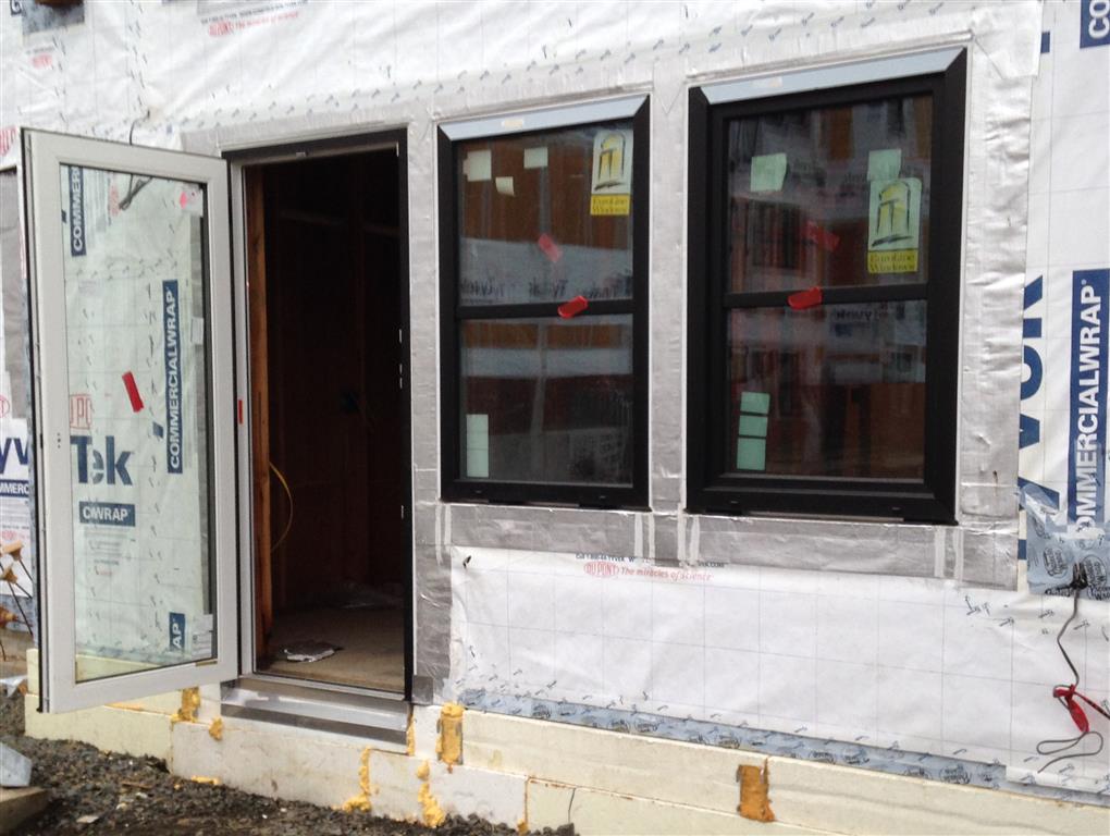
High performance windows and doors are central to the energy design concept at the Orchards project.
The interface between windows and walls plays a critical role in whole building airtightness. On many buildings, this is one condition where much of the air leakage occurs. To provide air barrier continuity at Orchards, we installed wet sealant between the window frame and the rough opening flashings all around the interior perimeter of the window frames. To flash the rough openings, we used a self-adhered rubberized asphalt membrane (SAM) product, Protecto Seal 45, combined with prestrips of water-resistive barrier (WRB) material. This membrane was specified because it has a foil facing that facilitates adhesion with the silicone sealant used to make the seals. The sealant we used – Dow Corning CWS – adheres extremely well to the foil facing and also to the fiberglass-vinyl window frames. The initial design details did not call for it; however, during construction the team agreed it was prudent to add another seal around the exterior perimeter of the window frames at the jambs and the head, to minimize the potential that exterior moisture could enter the gap between the window and the wall.
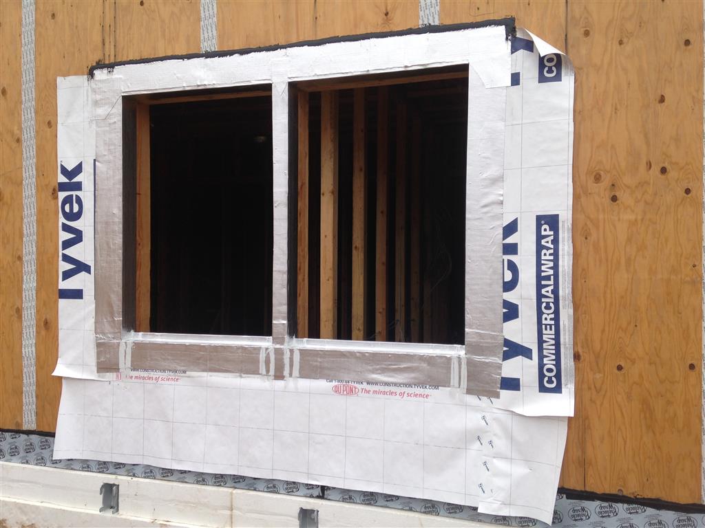
Typical rough opening preparation prior to window placement. Strips of water resistive barrier (WRB) material are installed, then foil-faced SAM flashing is used to wrap the openings for water management and airtightness at this crucial interface.
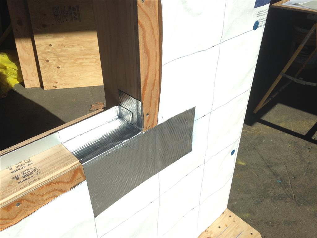
WRB material is held back 2” from the edge of the openings so that SAM is adhered to the sheathing prior to lapping the WRB. This provides for air barrier continuity. Note the SAM sill pan flashing in progress.
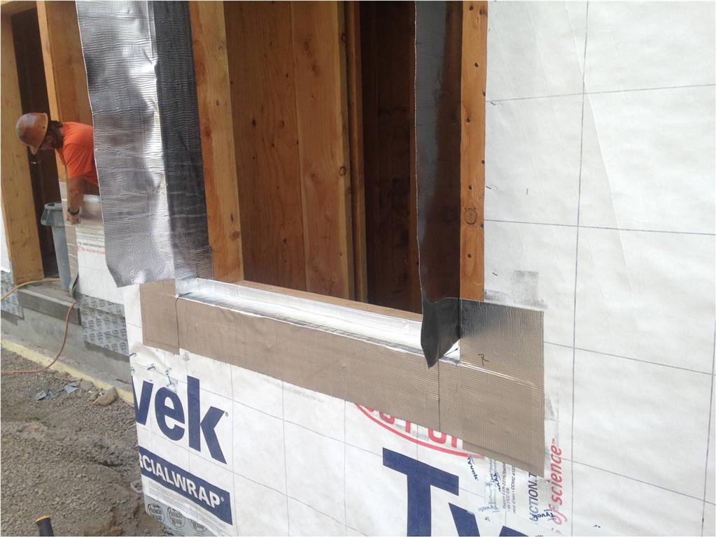
Sill pan flashing is complete. SAM flashing is applied to the jambs. SAM primer is applied to all substrate materials prior to adhering the SAM.
During the design phase, the team studied where best to position the windows within the wall. One approach we looked at was to place the exterior face of the window frames flush with the face of the sheathing, to allow the exterior insulation layer to extend over the frames. Several iterations of the PHPP model indicated significant benefit to “overinsulating” the windows in this manner so the team agreed to proceed in this manner. We then encountered some constructability issues; however, especially at the interface between the window sill and the wall. With typical detailing, the face of the window frame is positioned outward an inch or two from the face of the sheathing, which allows for joining the metal sill flashing to the window frame outward of the sill pan flashing. This is important to maintain free drainage from the sill pan. With the Orchards detail, we had to bring the horizontal leg of the metal sill flashing into the sill pan area to create the sealed joint with the window frame. To do this, we needed to shim the windows higher than is typical to provide the clearance in the sill pan area to allow for the joint but also to allow for free drainage from the sill pan. We used two stacked, stepped shims to accomplish this and it worked quite well during the window installation.
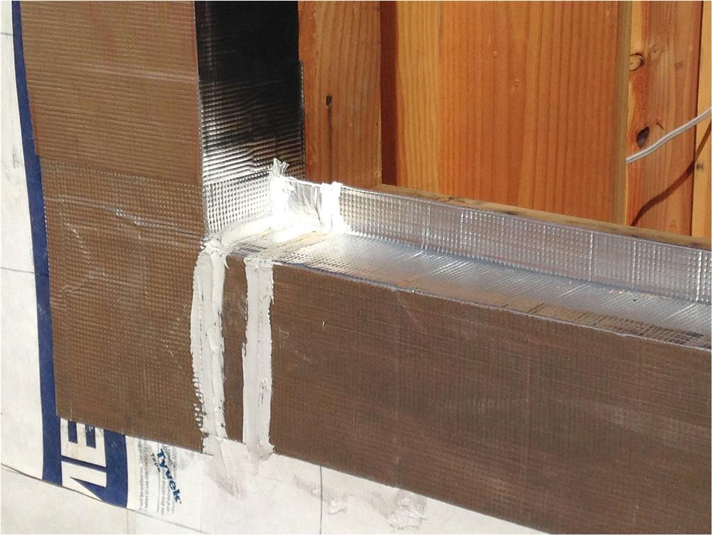
Detail view of sill pan flashing. The back leg of the pan is supported on the aluminum angle provided by the window manufacturer for attachment of the window sill.
Detail view of the SAM flashing wrap at jamb and head.
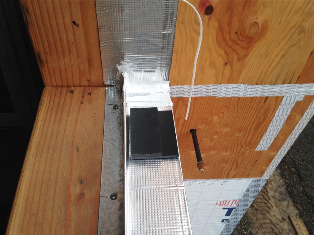
View of sill pan showing two-stage shim. This set-up allows the metal sill flashing to enter the gap between the sill pan and the window frame while maintaining the gap for drainage.
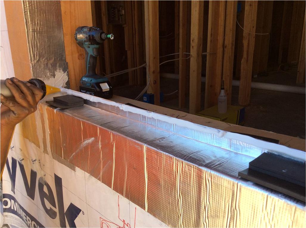
Sealant is applied to the back leg of the sill pan prior to setting the window into the opening.
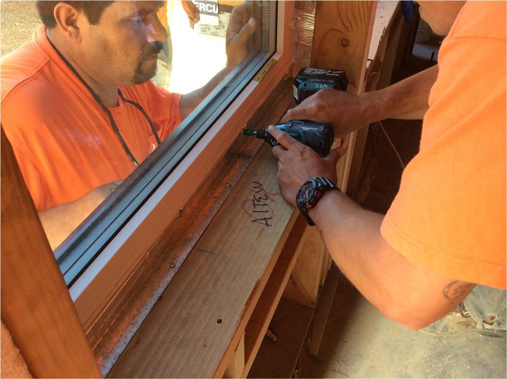
Window is fastened at the sill using an aluminum angle provided by the window manufacturer. The angle also serves as support for the SAM sill pan.
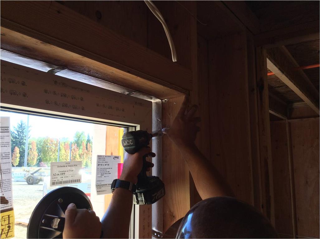
Window is fastened at the jambs and head using strap anchors provided by the window manufacturer.
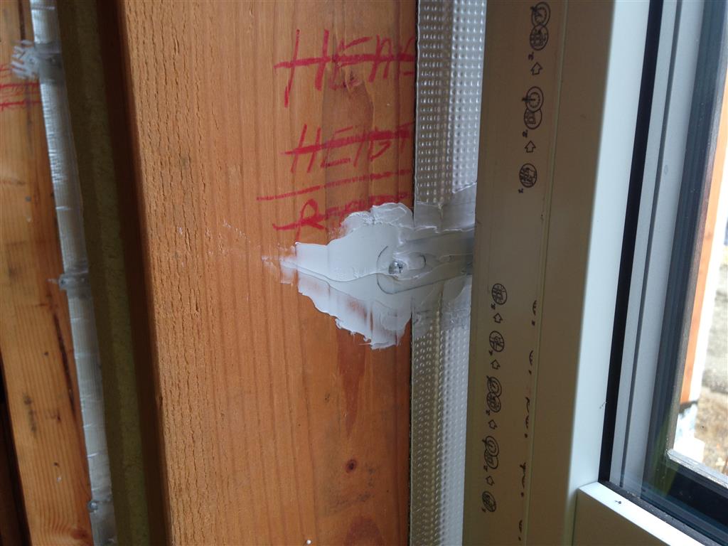
Sealant applied to strap anchor after fastening. Backer rod and sealant is subsequently installed in the gap between SAM flashing and window frame.
Air and water seal at interior perimeter of window. This seal completes the air barrier continuity from the wall to the window.
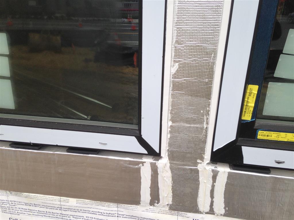
Water seal at exterior perimeter of windows. These seals occur at the jambs and head of each window. The sill is left open to allow free drainage from the sill pan area.
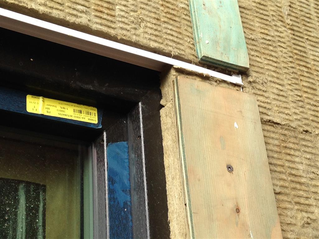
Metal sill flashing (cutaway view at mockup). The flashing is inserted into a cavity at the underside of the window frame. Bond breaker tape and sealant is then applied at the gap. The flashing is placed on the lower of the two shims to provide support and maintain free drainage from the sill pan area.
At the window head, the architect’s detail called for a rigid PVC head flashing and a specific SureSill flashing product had been called for due to its three-dimensional configuration. Typically we use brake-formed metal flashing at the window head; however, there was concern from the design team that metal flashing would cause too much thermal bridging. The construction team anticipated we’d be able to source this flashing with relative ease from a local supplier and that was the case when we ordered three 48” long pieces for our mockup. However, after working through the mockup, the team determined a single ten foot long flashing piece covering both the window head and the adjacent balcony door head would work best. A significant glitch ensued. The local supplier did not have the ten foot lengths of flashing in stock. And then when we placed an order with the Florida-based manufacturer, we were told they didn’t have the quantity we needed and put us on back order. The product is actually manufactured in China and, after several communications with Florida, we learned our flashing was literally on the slow boat to the US! At this point, our siding installation was scheduled to begin in a week. Not good. To add a little more pain to our suffering, the order got hung up a few extra days in customs. Six weeks later the flashing arrived on site and the siders began their work. Fortunately we were able to move forward with WRB installation well ahead of the siding and got the building in the dry without delay, but the lag time on the flashing delivery had some unanticipated impacts on our proposed sequencing of work. Lesson learned: make extra sure that thermally non-conductive flashing material is needed for your passive house design. And, if so, make sure they have adequate stock at your supply house of choice.
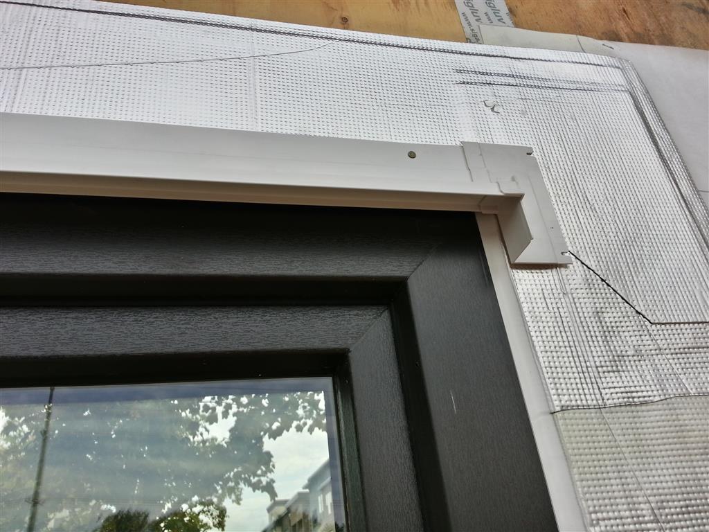
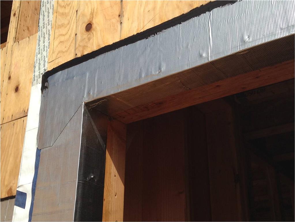
PVC head flashing with preformed end dam is installed directly above the window frame. WRB from the wall area above the window is then folded down to lap over the head flashing.
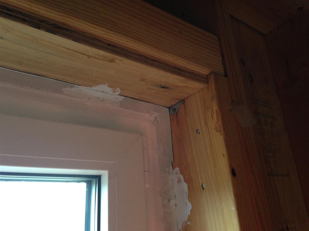
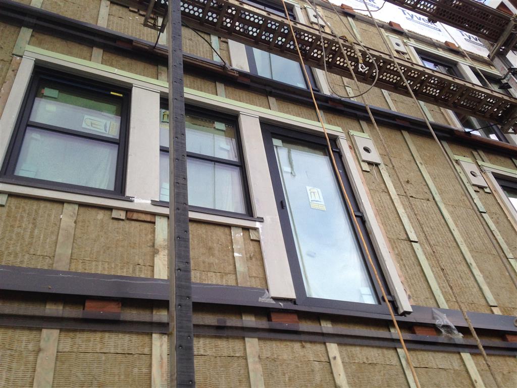
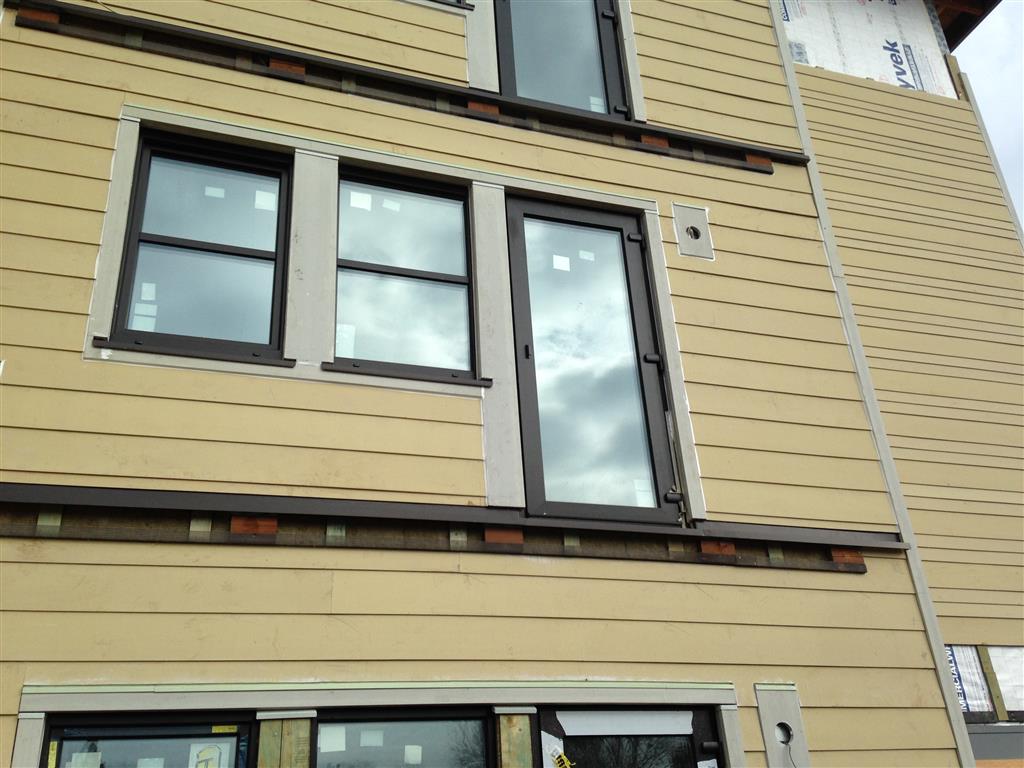
View of typical window head/jamb condition showing treated plywood furring at jamb and PVC head flashing, integrated with mineral wool exterior insulation layer. The mineral wool extends 1 ¼” over the window frame at the jambs to “overinsulate” the frame and improve thermal performance.
The patio/balcony doors are essentially just large tilt-turn windows, configured as doors. Exterior doors typically do not have the airtightness and water resistance to match windows, but these are not your typical doors! With three compression gaskets the sash seals tightly to the frame, and the pressure-equalized rainscreen design is developed to manage water extremely well. The owner’s representative commissioned testing of the doors and windows by an independent agency, and the doors passed field water tests up to the specified requirement of 6 psf. After passing the required level of watertightness, the test agents ran the pressure up to 12 psf and the doors still did not fail.
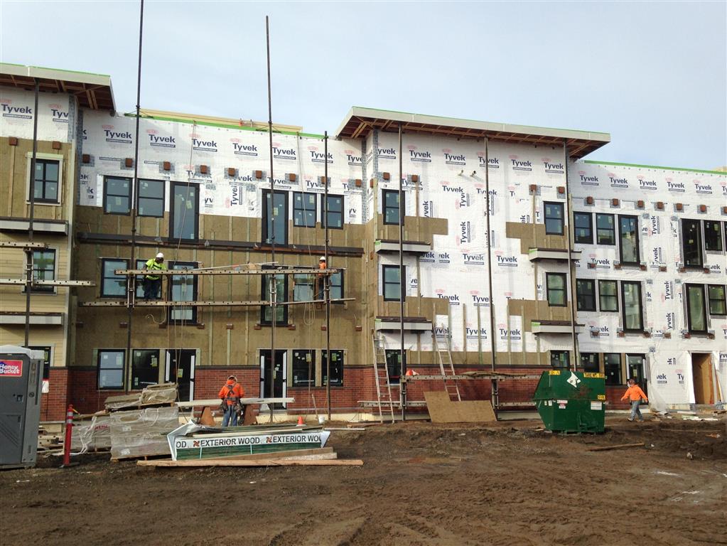
After completing the window and door installation, we installed a spun-bonded polyolefin sheet membrane (Tyvek CommercialWrap, manufactured by DuPont) over the sheathing, taking care to integrate with the flashings around the window and door openings to ensure proper overlaps for water management. The Tyvek serves as the primary water-resistive barrier (WRB), and – combined with self-adhered membranes and various flashings – forms a complete water-resistive barrier system at the exterior walls. Given the high level of airtightness and insulation at these walls, and thus the lack of drying potential, it is critically important to manage against water infiltration into the moisture sensitive areas of the wall system. An intensive quality control effort was essential to ensuring proper installation of the water-resistive barrier and all related flashings. Nick Kurkov – one of our most highly skilled enclosure specialists – was assigned the QC role, working closely with Jeremy Brooks, our superintendent who shouldered primary responsibility for managing all the work on site.
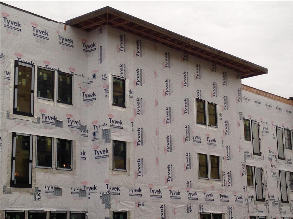
Spun-bonded polyolefin sheet membrane WRB is installed over the balance of the exterior wall assembly and carefully integrated with all previously installed flashings around the window and door openings to ensure proper overlaps for water management. SAM reinforcements of the WRB membrane can be seen in the balcony areas where intermittent blocking is soon to be installed.
There are 36 balconies on the building, providing private outdoor living space for all residents. One of the most challenging details was how to structurally connect the balconies to the primary structure while minimizing thermal bridging and also managing water. The design solution was to provide a continuous ledger around the balcony similar to typical construction; however, the ledger is fastened to intermittent 4×8 treated wood blocking that is installed at 4’-0” spacing. By allowing us to install mineral wool exterior insulation behind the ledgers and continuously over the backup wall, this detailing maintains our thermal barrier continuity at the balcony to wall interface except at the block locations.
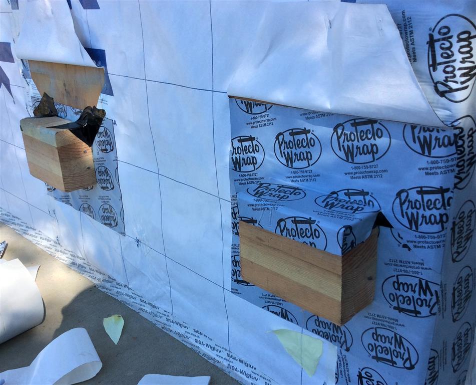
Treated wood blocks – spaced intermittently at 48” o.c. – are installed over continuous WRB at the balcony areas and where “eyebrows” (sunshades) occur. These blocks are structurally attached to the backup wall and then the balcony ledgers and eyebrow framing are attached to the blocks. This allows the exterior insulation layer to extend nearly continuously over the exterior wall assembly. SAM saddle flashing is installed over each block to protect the blocks, and the fastener penetrations, from excessive exposure to moisture.
Prior to installing any balcony framing (including blocks), we installed the WRB system continuously over the walls at the balcony areas. The blocks were then installed over the WRB layer and then were subsequently fitted with saddle flashings that we integrated back into the WRB. Metal through-wall flashing was then installed above the line of blocks at each balcony and the siding installation commenced. The actual balcony joist framing and decking was installed last, after completion of the siding and trim.
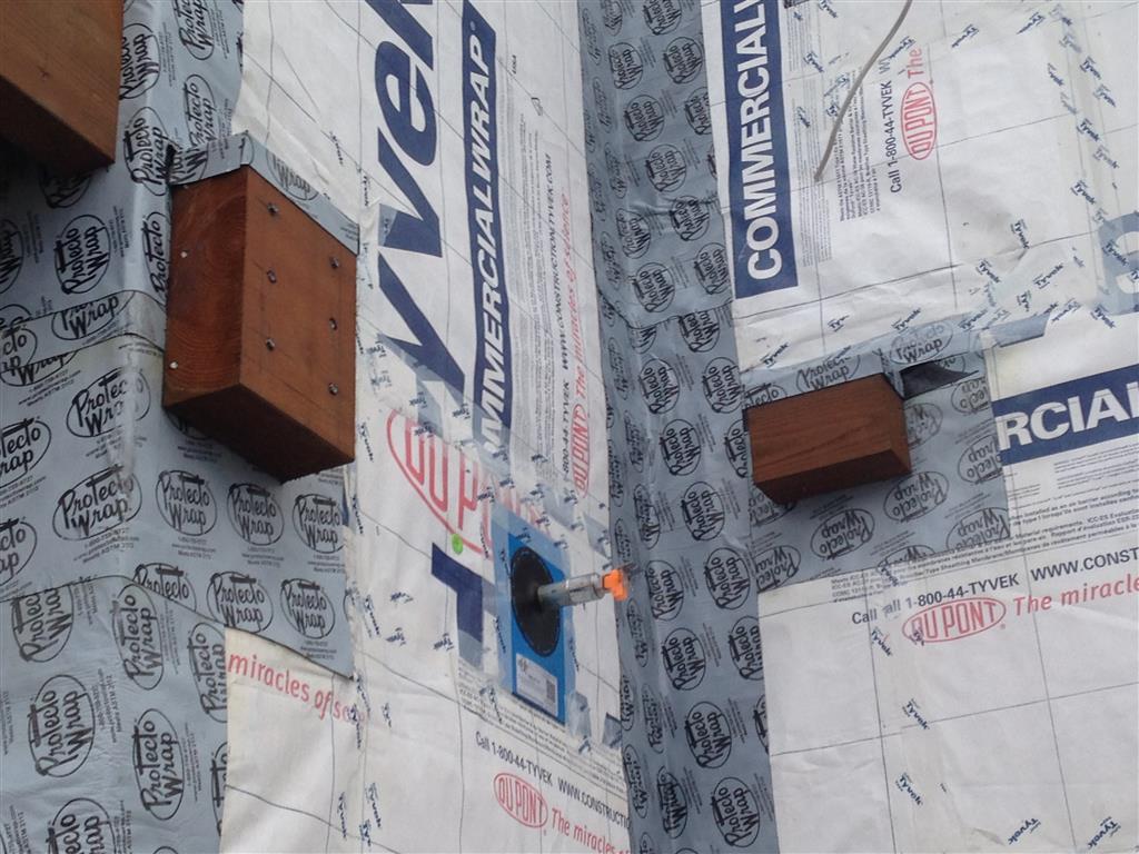
View of balcony area showing typical ledger blocking at right. A sprinkler head penetration is sealed with a Quickflash specialty flashing that has been woven properly into the WRB layer. The block that appears on the left will receive the main beam that supports the balcony joist framing. All blocks are protected with saddle flashings fabricated on site with SAM membrane.
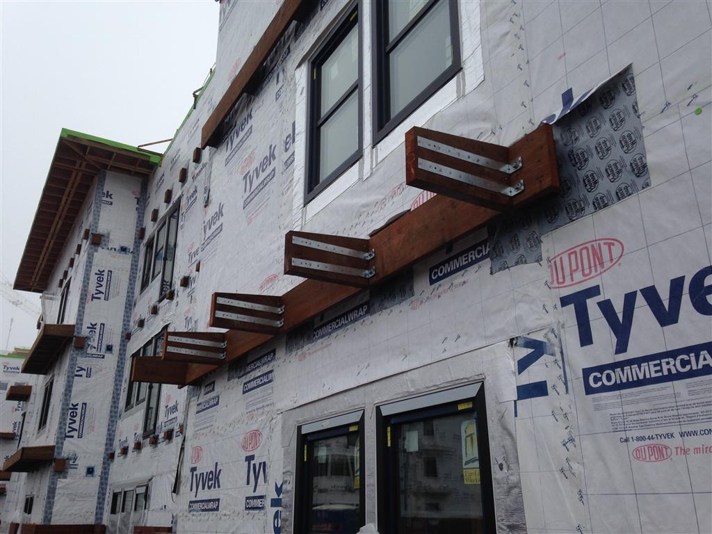
View of eyebrow element framed with treated wood. The ledger is attached to intermittent blocking. The eyebrows shade the windows to mitigate overheating during the summer months.
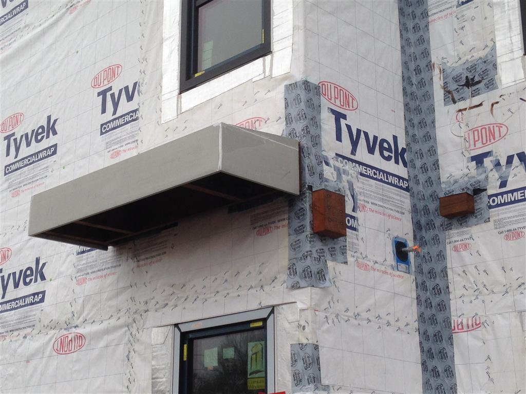
Eyebrow element with fiber-cement trim finish, prior to installation of metal flashing and roofing.
Roofing and Cladding
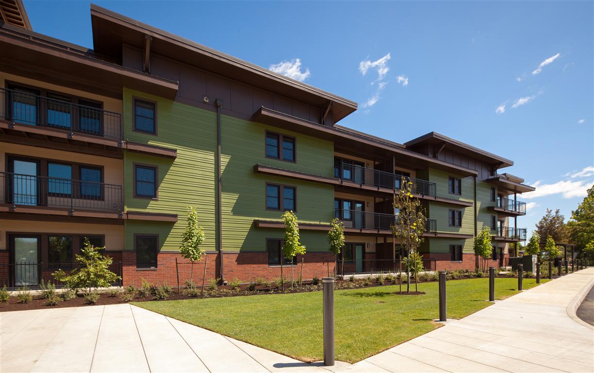
The Orchards at Orenco displays a mix of brick veneer and fiber-cement claddings. Balconies and “eyebrow” elements are designed to shade the windows and doors to mitigate overheating in the summer months but allow solar gain during the winter months. (Photo credit: Casey Braunger)
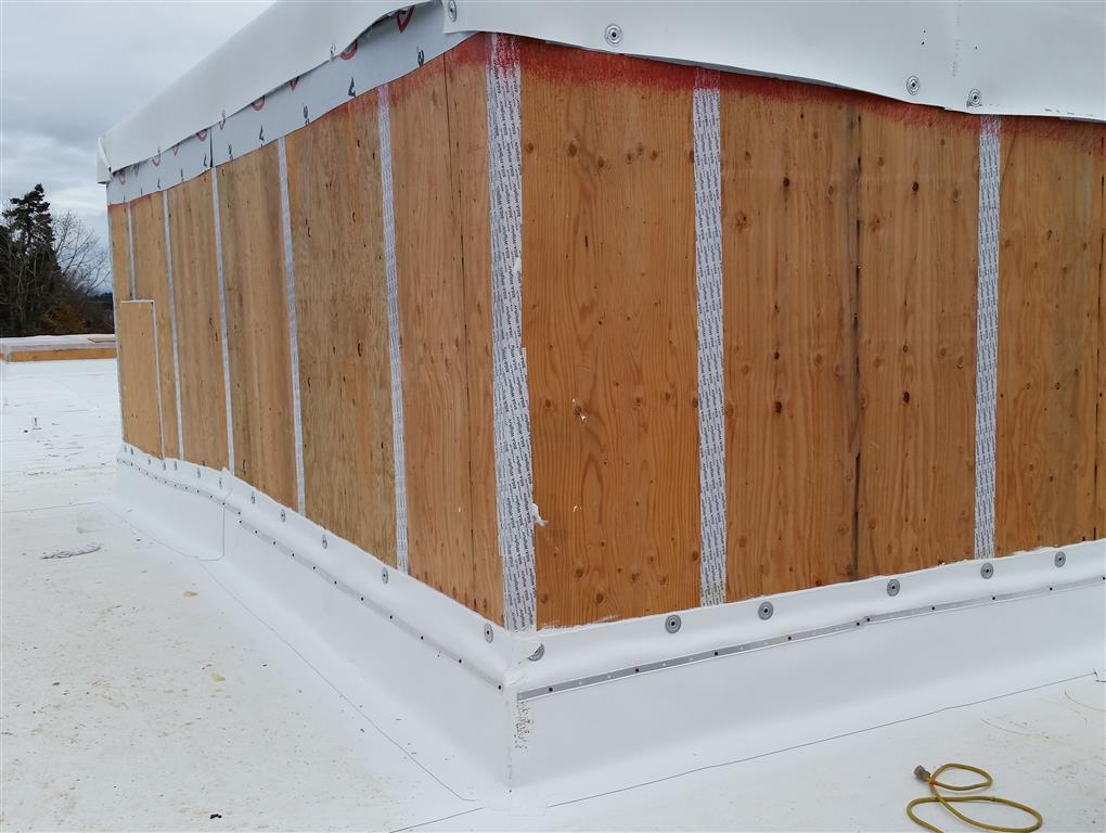
A highly insulated and airtight roof assembly tops off the Orchards building enclosure. Overall the roof construction was very straightforward, although the parapets complicated things somewhat due to the architectural expression of the cornices. Once the trusses were placed, they were sheeted with plywood. At the edge of the roof, we carried out a simple detail that ultimately would help us to achieve a very high level of airtightness. Experiences on a number of previous projects had taught us that the joint between the wall and roof is one of the most problematic areas to maintain air barrier continuity. Therefore, a considerable amount of time was spent early during design to discuss this issue and to develop a conceptual approach to the wall to roof joint. Typically, parapet walls on wood frame buildings are framed as an extension of the roof truss framing; however, this standard approach prohibits a simple, constructable and effective detail for transitioning the plane of airtightness from the wall sheathing to the roof sheathing. Working with the design team we came up with a concept where the parapet walls would be framed as separate components placed on top of the roof sheathing and fastened to the roof framing, but this would be done only after the air barrier had been transitioned from the wall to roof at the sheathing planes. The final detail follows the initial concept very closely.
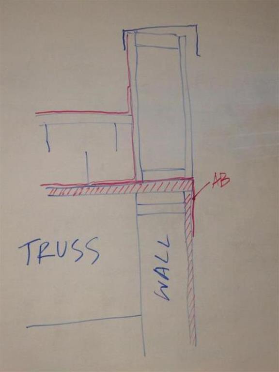
Concept detail developed early in design process to address need for air barrier continuity at the critical wall to roof joint.
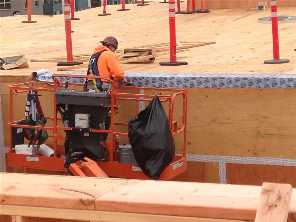
SAM is applied at the interface between wall and roof. This essentially completes the seal of “the box” by connecting the wall sheathing to the roof sheathing.
SAM transition seal is applied to the top of “the box.” Note the poly sheeting to the right. It has been placed temporarily to keep the sheathing dry prior to installation of the membrane.
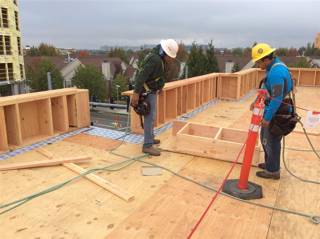
Parapet wall framing is installed over the SAM transition seal. SAM extends several inches outward from the inside face of the parapet to facilitate the tie-in with the SAM vapor barrier / air barrier to be installed later over the roof sheathing.
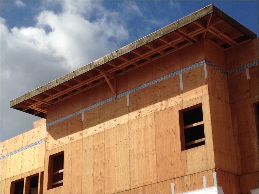
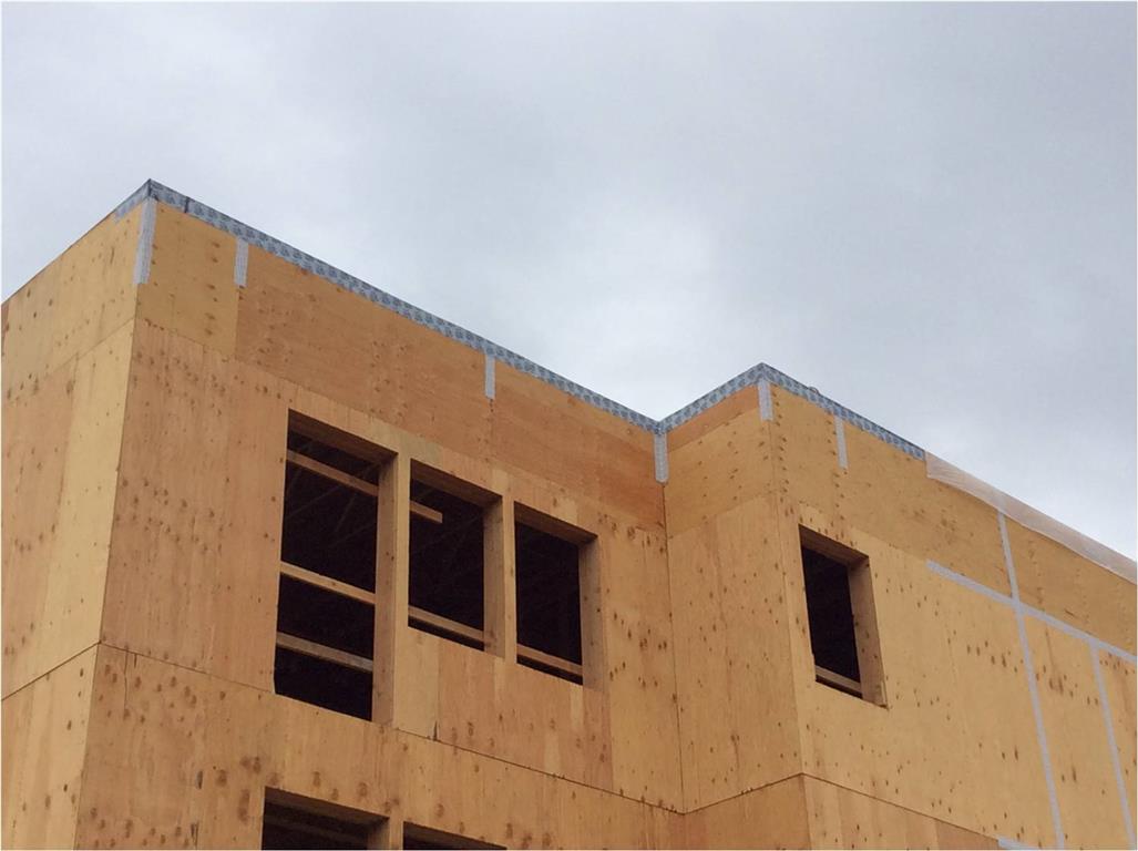
View of parapet walls framed on top of “the box.” Once the joints in the wall sheathing are taped, the windows are installed and sealed, and SAM is installed over the roof sheathing, the air barrier system will be largely complete.
Once the roof framing was complete, including the parapet walls, we then installed a self-adhered rubberized asphalt membrane (V-Force, manufactured by Firestone) over the roof sheathing and several inches up the faces of the parapets. This membrane serves multiple functions as a vapor barrier and air barrier for the roof assembly but also served as a temporary roof to help keep the building interior dry until we could install the insulation and permanent roof membrane. All service penetrations of the roof, such as plumbing vents, were sealed to the self-adhered membrane with wet sealant. Three layers of 4” polyisocyanurate rigid insulation were then installed over the self-adhered membrane. The base layer was screwed into the roof trusses and the upper layers were then adhered to each lower layer, thus minimizing the impact of thermal bridging through the fasteners. Joints in the insulation boards were staggered to further prevent any potential thermal leakage paths. Once the insulation had been laid, a coverboard was installed and then the 80 mil single-ply roof membrane (UltraPly TPO XR 135, manufactured by Firestone) was fully adhered to the coverboard. The total R-value of the roof assembly is R-78.
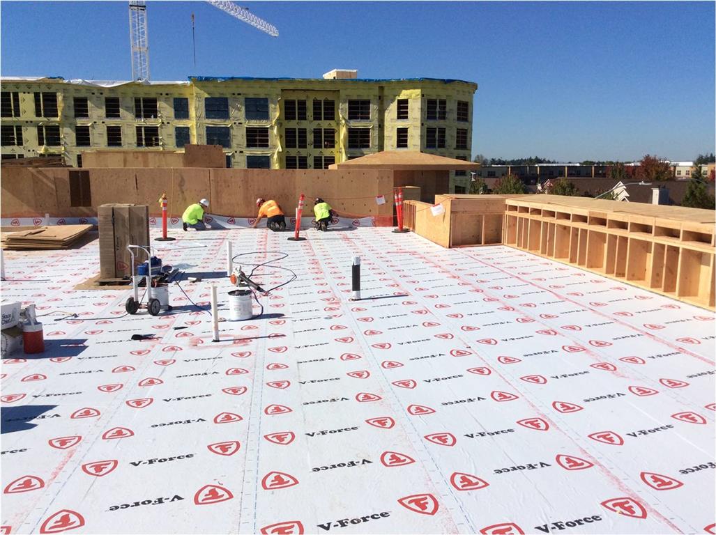
SAM vapor barrier / air barrier installed over the roof sheathing. This sheet membrane laps over and seals to the SAM transition seal installed around the roof perimeter. The membrane also serves as a temporary roof prior to placement of the roof insulation, coverboard and TPO roof membrane.
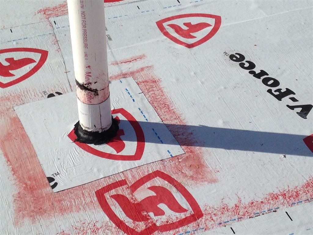
SAM collar and sealant is installed at the plumbing vent penetrations of the roof air/ vapor barrier.
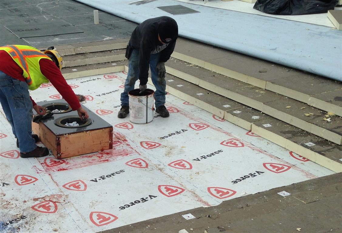
Vapor barrier, insulation layers, coverboard and roof membrane at a drain location in the roof assembly.
The completed roof membrane, prior to installation of WRB, furring and siding at one of the mechanical penthouses. The walls and roofs enclosing the three mechanical penthouses are all part of the passive house enclosure.
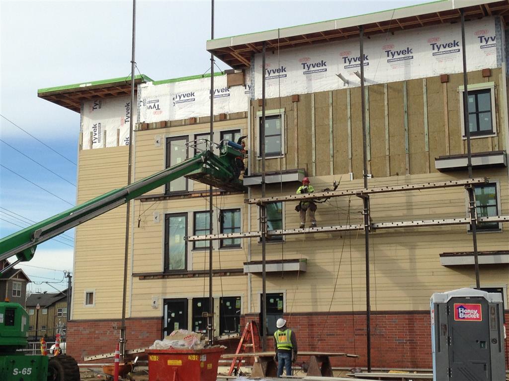
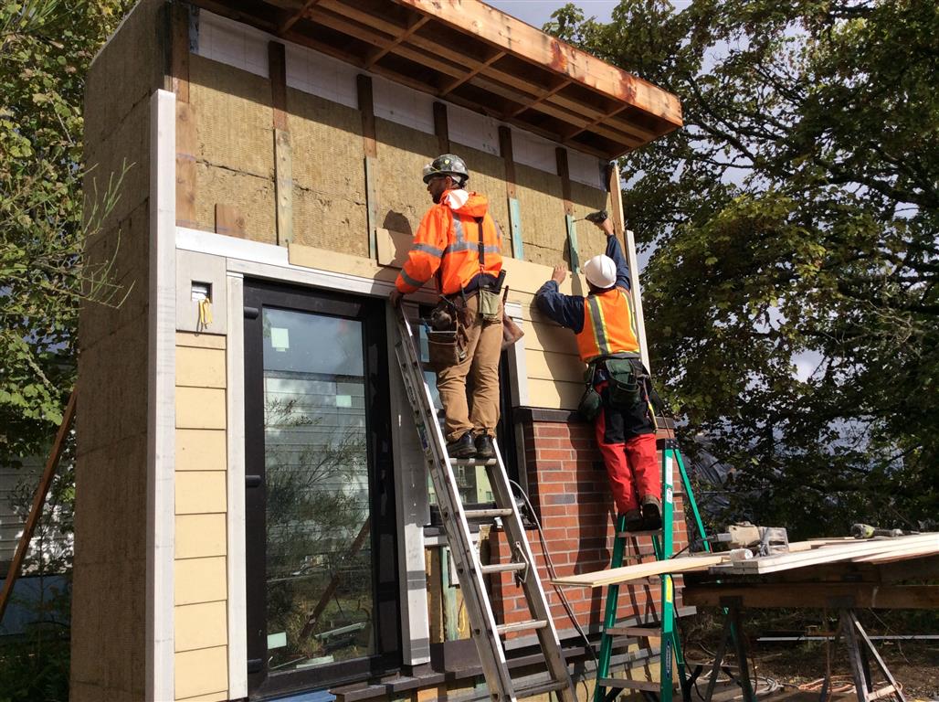
The building is clad in fiber-cement siding and brick veneer. Prior to placing the actual cladding materials, the masons and siders first installed a 1 1/2” thick layer of 8 lb. density mineral wool insulation over the WRB. The masons used Rockboard 80 and the siders used ComfortBoard IS. Both products are manufactured by Roxul. Stainless steel masonry anchors were installed over the WRB and penetrate the exterior insulation layer, creating minor thermal bridges. At the siding areas, ¾” thick x 3” wide treated plywood furring strips were installed over the continuous insulation layer. The siders then nailed the fiber cement planks to the furring with stainless steel siding nails. The structural engineer of record for the project – Scott Nyseth of Stonewood Structural Engineers – designed the attachment of the furring to the backup wall: #12 hot dip galvanized screws, 4 ½” long, fastened at 16” o.c. vertically in line with the wall studs. Initially the siders encountered difficulties in terms of getting the furring to lay flat on the mineral wool. It took some time for the crew to get a good feel for the proper amount of drive on the screws to achieve a flat application. On early mockups of the exterior wall we had identified this flatness issue, noting that plywood furring in particular was susceptible to compression into the mineral wool layer. We found that 1×4 furring when installed over the high density mineral wool was more rigid and did not exhibit the compression problem. However, the siders were concerned about splitting with the 1×4 material and pushed for using the plywood instead; this was agreed to by the design team.
In progress view of siding installation, showing WRB, exterior insulation and furring.
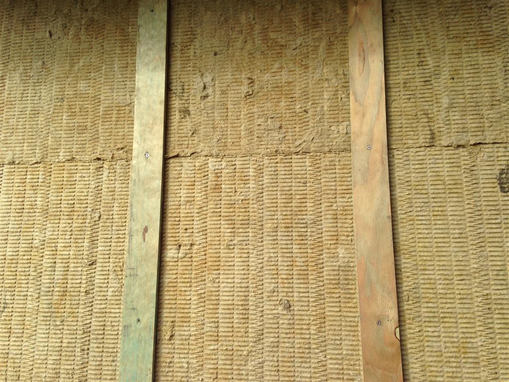
Detail view of treated plywood furring installed over mineral wool insulation.
Roxul has issued fastening guidelines and now recommends 2×3 or 2×4 furring for siding installations over semi-rigid mineral wool. Although 2x material is not necessary for structural attachment of the siding, it would certainly help with maintaining a flatter application of the furring and limiting the potential for splitting.
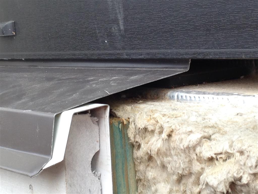
Exterior insulation and rainscreen furring at balcony area. Metal through-wall flashing is installed above the intermittent wood blocking. A strip of brake-formed perforated metal is installed at the floor line just below the through-wall flashing and serves to ventilate the rainscreen cavity at the top of the siding below each balcony.
Similar wall area seen after siding installation. Soon afterward, 2×10 continuous ledgers will be fastened to the intermittent blocking and then balcony joists and decking will be installed.
When installing exterior insulation, the mineral wool boards can be difficult to cut to size to fit tightly around windows and penetrating items at the wall. With a bit of research we were able to locate a tool made specifically for this application and offered it to the subcontractors to assist with the cutting process. This tool – called the SkärBord insulation cutting table – is manufactured in Sweden and is sort of like a large miter box for insulation material. It allowed the trades to make quick, accurate cuts of the material, which helped us achieve a very high quality installation.
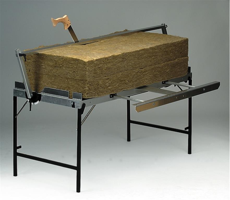
Skärbord mineral wool cutting tool. (Photo credit: Bygghouse)
Brick veneer generally only occurs at the base of the walls, extending four feet or so up the facade. In typical construction, brick veneer is supported on a “ledge” that is cast into the concrete foundation at the building perimeter; however, this approach creates a large thermal bridge through the enclosure. To minimize thermal bridging at Orchards, the brick veneer is instead supported on a continuous 4” x 4” galvanized steel ledger angle that has been thermally isolated from the primary structure, using off-the-shelf steel FAST brackets (manufactured by Fero Corporation), installed at 3’-0” on center along the concrete foundation around the base of the building. By using these brackets, we were able to apply the expanded polystyrene insulation in a continuous layer over the exterior side of the concrete foundation.
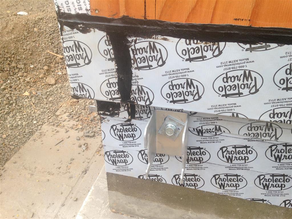
View of steel support bracket at base of wall where brick veneer occurs. The brackets are installed at 3’-0” on center.
Excess spray foam is trimmed away and a 4×4 steel ledger angle is placed into the brackets.
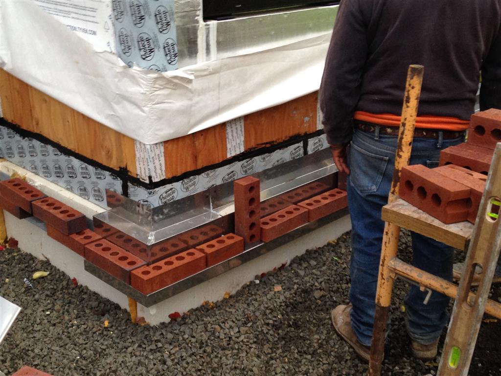
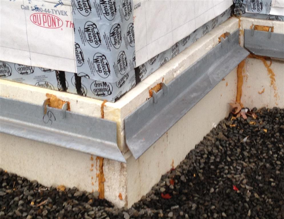
The ledger angle is covered with stainless steel base of wall flashing and then the brick veneer installation proceeds.
Once the building was dried in, we began the interior finish sequence. Netting was installed over the exterior wall framing and fiberglass insulation was then blown into the 2×10 wall cavities. A polyamide sheet material was then stapled up on the walls over the netting. We used Membrain, a specialty vapor barrier product manufactured by Certainteed. Prior to installing the gypsum board interior finish, the insulation was inspected by both the local building department and Earth Advantage, the PHIUS+ rater for the project. After factoring in the advanced framing methods and details, the 9 ¼” of blown fiberglass and the 1 ½” of mineral wool exterior insulation, the total R-value of the exterior walls is 39.
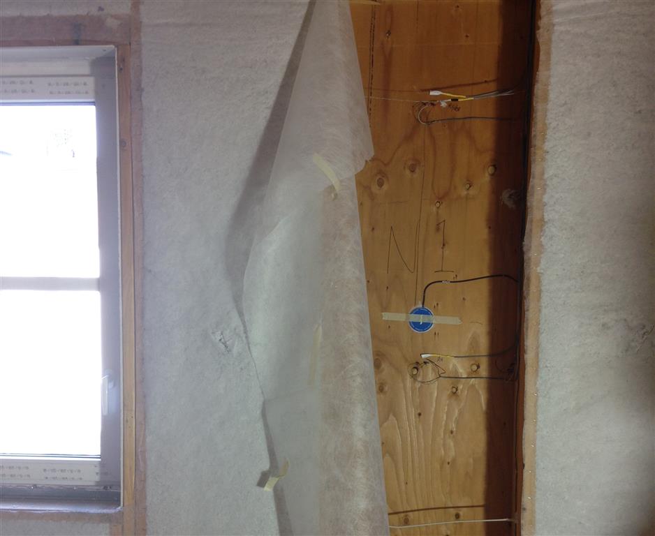
Fiberglass insulation is blown into the exterior wall framing cavities through netting material. Here the netting has been pulled back and the insulation removed at one framing cavity to allow the installation of relative humidity sensors and moisture content pins. A monitoring program – using these sensors and pins that are installed at several cavities, and in the exterior insulation layer, around the building – will provide data on the moisture and thermal performance of the exterior wall assembly.
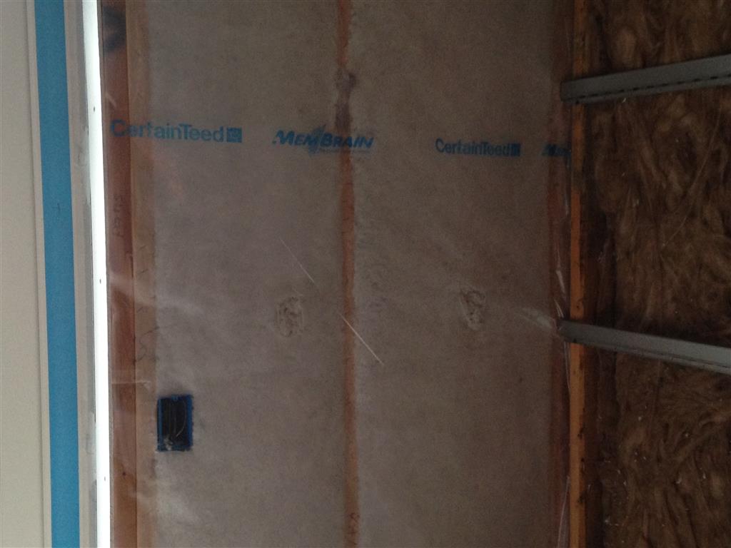
Framing and insulation at the exterior walls is covered with a polyamide sheet vapor barrier material.
An important quality control issue arose during construction: how to best verify the quality of the blown fiberglass installation in the 9 ¼” wide wall cavities. The material was specified to be installed at a certain density; however, it was difficult to inspect this visually. To some degree the density can be checked with a simple “mattress test” by placing one’s hand on the netting and pushing on the installed insulation to “feel” the density, but this is a subjective assessment. Travis Moore, our clever project engineer, developed a crude but effective measuring device to provide a more objective assessment: a sampling box constructed of sheet metal and tape that allowed for a number of random inspections of the installed density. The box was pushed through the netting and insulation, and then pulled back out of the wall cavity, thereby removing one cubic foot of installed insulation. The box was then weighed on a scale to determine the as-installed density. A log was developed to record the sampling done during the course of the installation. Through a combination of visual inspections and random sampling with Travis’ box, we identified a number of wall areas that needed additional insulation and the insulation contractor returned to blown in more fiberglass.
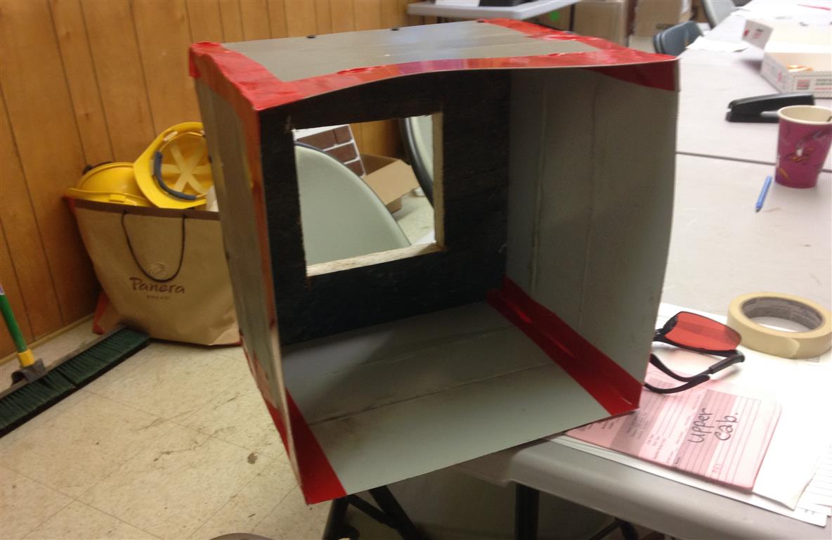
Travis’ insulation sampling box fabricated from sheet metal and construction tape.
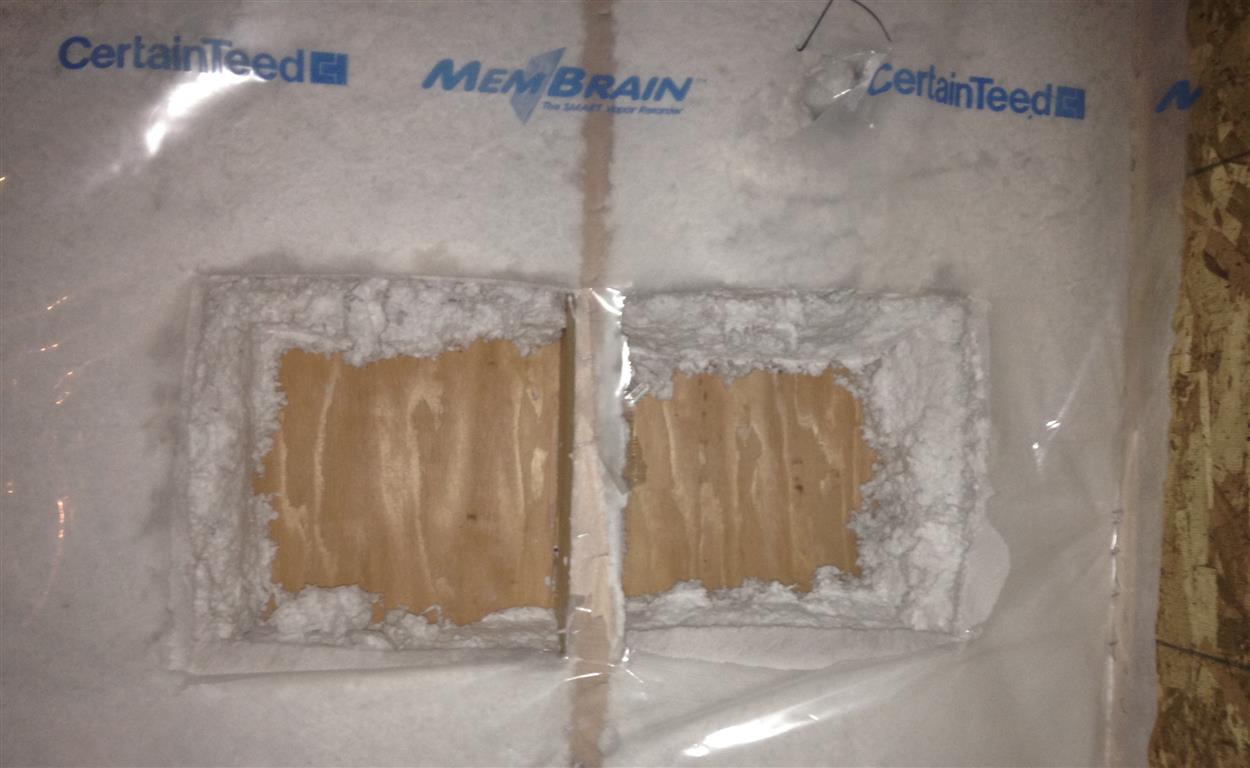
Insulation density test locations
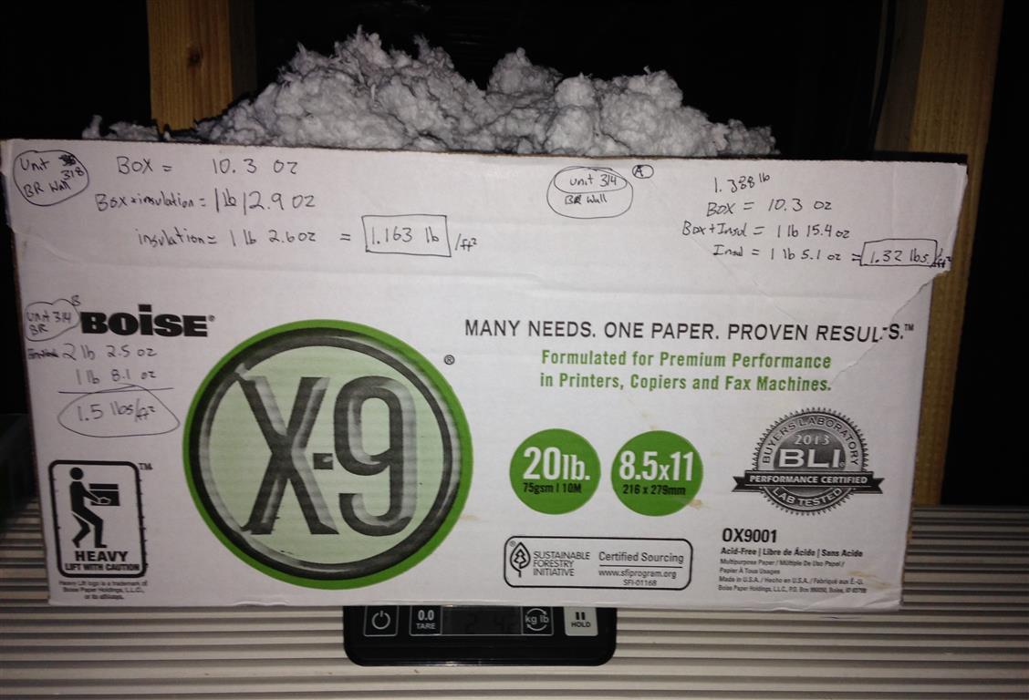
Quality control sample is weighed in specimen box.
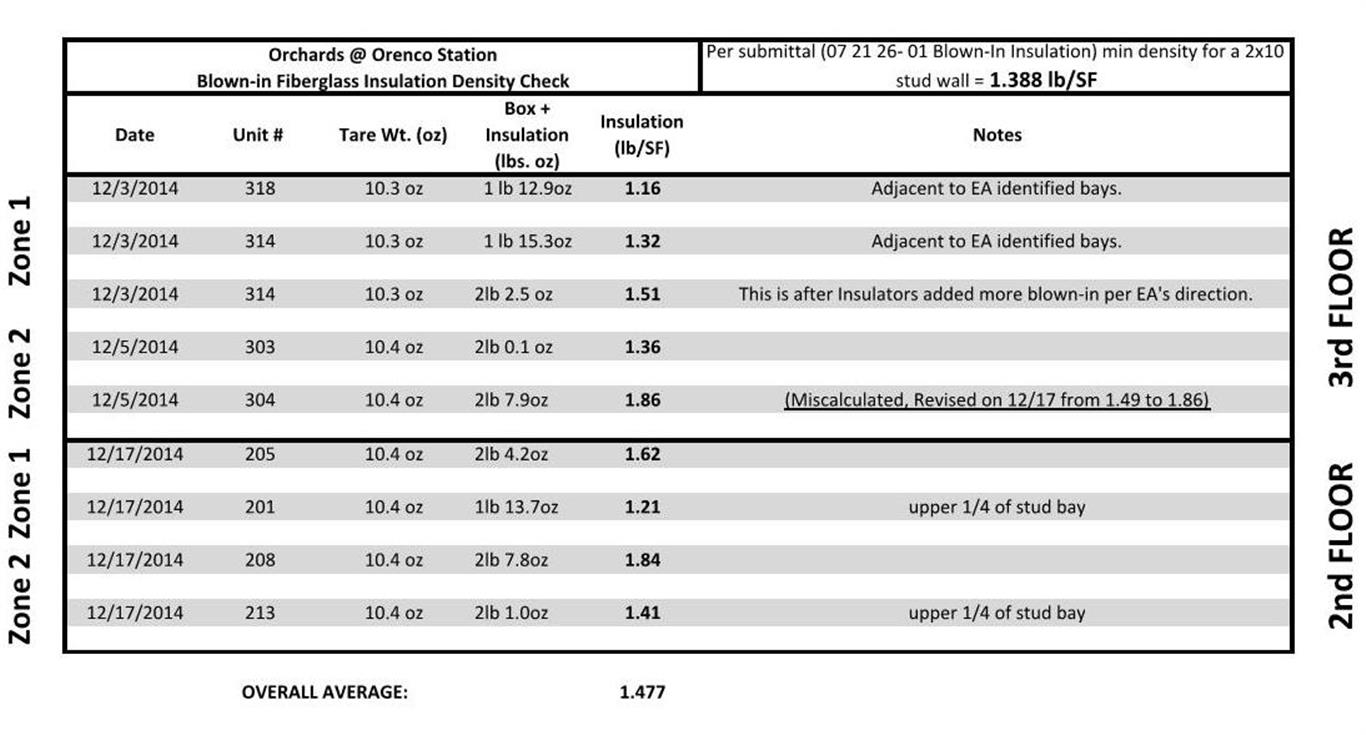
Insulation density test log.
A series of design measures were integrated into the exterior walls to enhance moisture performance and durability. As required by the Passive House standard, a high level of airtightness (0.6 ACH50 max.) was specified to limit the potential for condensation within the wall interstices. Also, in the specification of materials and products for the exterior wall there was a continual stress on vapor permeability, to maximize drying capacity: a “flow through” design concept if you will. The exterior insulation layer was utilized to limit thermal bridging but also to help keep the temperature of the wood framing and sheathing above the dew point for nearly the entire year. A mineral wool product was specified rather than XPS or EPS due to its high vapor permeability, given its application on the exterior side of the wall. The Tyvek CommercialWrap WRB material with very high vapor permeability (28 perms) was specified to facilitate drying to the exterior as well. Plywood sheathing was chosen in lieu of OSB due to its higher wet cup perm rating (approx. 10 perms). And lastly, the Membrain vapor barrier product was specifically called for at the interior side of the wall – rather than the polyethylene sheet or kraft paper that is typically used – in order to facilitate drying to the interior should there be any moisture remaining in the wall upon completion of construction or should small amounts of moisture enter the wall in service.
Early on during construction we worked with Building Science Consulting Inc. (BSCI) and Roxul to establish a program to monitor the moisture performance of the exterior walls. As the interior finish cycle began, BSCI came to the site and installed sensors, pins and other instrumentation to serve the monitoring study. RH sensors and moisture content pins were placed in southward-facing wall cavities at two adjacent apartments on the third floor of the building. The same application went into place at north-facing wall cavities in the two apartments across the hall. Sensors were also placed on the face of the WRB material and within the exterior insulation layer at the same wall locations. Sensors and pins will measure moisture content, temperature and relative humidity. Data collection is planned for a period of one to two years. Analysis reports, findings and conclusions will be available from Roxul at a future date.
A forthcoming blog post will report on the whole building airtightness testing process and results at Orchards.
Unless otherwise noted, all photo credits to Walsh Construction Co.