It should go without saying that any high performance building should be built on a solid foundation. So why would we set our building on a layer of foam insulation? The answer of course is thermal bridging. Those bridging effects can cause a significant amount of heat loss through the mass structure at the base of the building. By thermally isolating the building foundation from the ground, building performance is improved, not only from an energy performance standpoint but also in terms of comfort and moisture management.
In some high performance building circles, it has become common to place a layer of insulation under the concrete slab-on-grade. This is especially the case in colder climates. What’s new with Passive House design is the idea of completely isolating the building foundation from the ground, not only under the slab, but also under the footings. As designers and builders getting our feet wet with Passive House design for the first time, our collective common sense suggested we be suspicious of this idea. Nearly all of the building’s structural loads are placed on the footings and it strikes many people as possibly a fool’s errand to place building footings on foam. However, after extensive research it became clear there is a long history of using certain types of very high density expanded polystyrene (EPS) foam insulation underneath major structural works of all kinds, including roadways, bridges and runways. Our concerns receded based on the evidence and we were swayed, yet reserved and cautious. The caution persists to this day and will follow us until this is a well established building practice, without significant drawbacks.
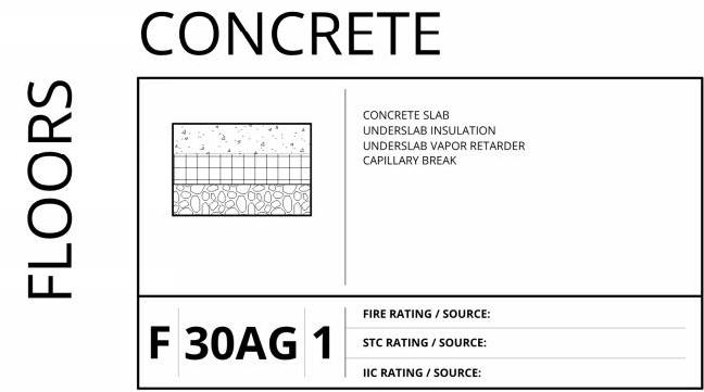
Typical concrete slab-on-grade assembly Image courtesy of Ankrom Moisan Architects
Once the team actually started believing this could work, the next concern became how much insulation to use. Together, we landed on the idea of 4” of EPS foam based on a sense this would provide a good balance of cost and constructability. In particular, we were trying to avoid the thicker levels of insulation that have been used on some passive house buildings. Throughout the design process, PHPP iterations were run that looked at using more or less foam foundation insulation yet the team kept coming back to the 4” foam layer. We looked at the relationship of the foundation r-value to changes in other envelope parameters such as the wall r-value, the window u-value, and the roof insulation. After numerous iterations, the 4” foam thickness was agreed to by the team. So, how does this work? The foam is placed under the entire slab-on-grade and wraps around and underneath the footings at the building perimeter. The 4” foam thickness is reduced to 1” at bearing wall locations, resulting in a thickened slab with reinforcement, to serve as footings for those walls at the building interior. Due to the seismic design of the project, there are several large, deep footings that serve as the base for hold downs to resist high lateral loads on the building. These deep footings were actually poured such that the slab insulation runs continuously over the top of the footing.
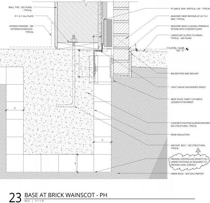
Image courtesy of Ankrom Moisan Architects
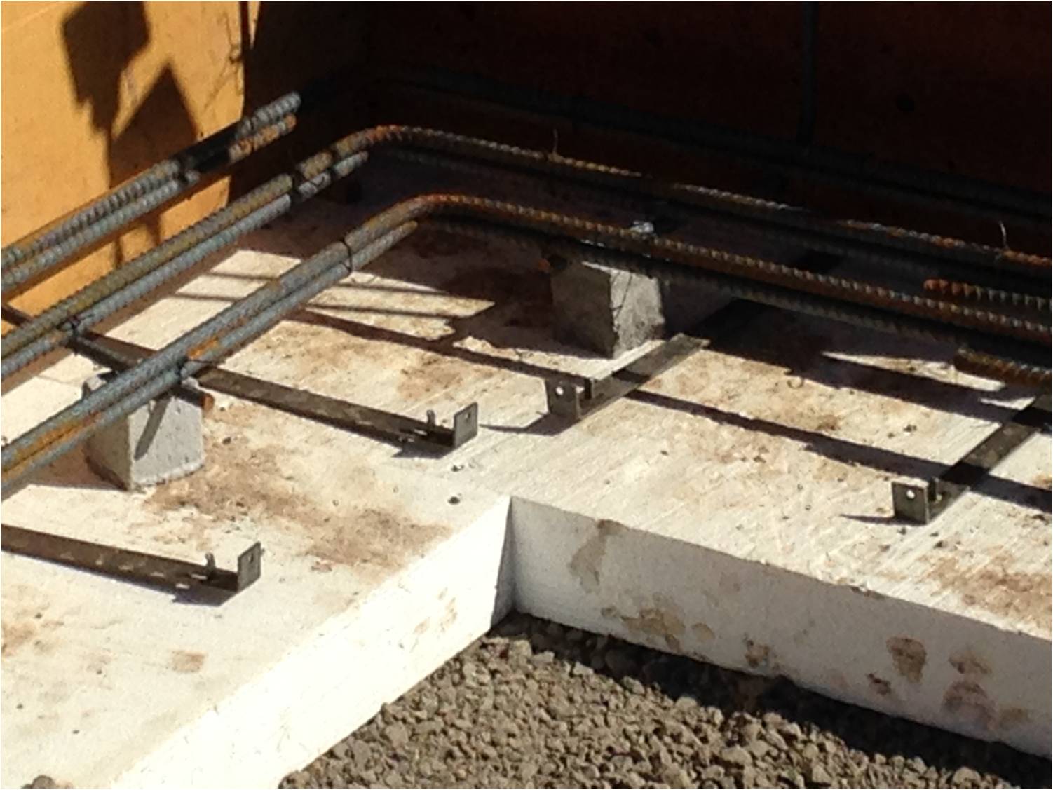
Base of wall detail, indicating typical perimeter footing. This is the typical base of wall condition, with brick veneer used as a “wainscot” around the building base, running to a height of approximately six feet. Instead of using a “brick ledge” configuration on the footing as is typical to provide support for the brick, a steel ledger angle is used. The angle is thermally isolated from the foundation by steel brackets, spaced intermittently at 4’-0” o.c. We used off-the-shelf “FAST” brackets manufactured by Fero Corporation.
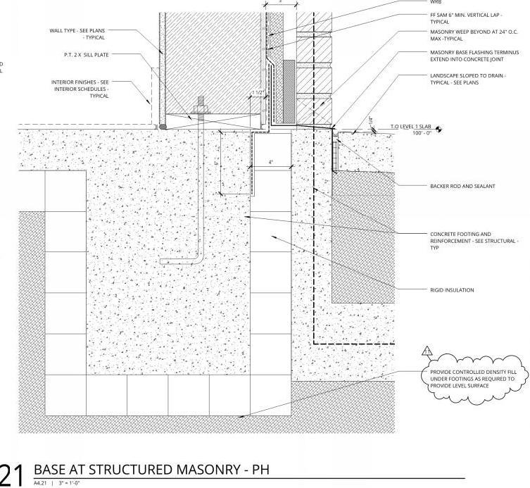
Base of wall detail at the few conditions where full height brick occurs. This is a structural brick veneer so a separate footing is required for structural support of the brick. Again, typically a brick ledge configuration would be used at the footing to provide support for the brick, but here a separate footing allows for thermal isolation of the perimeter footing.
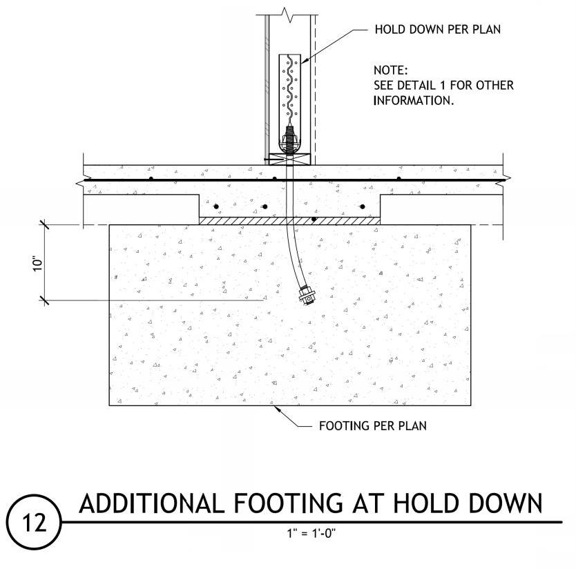
Image courtesy of Stonewood Structural Engineers
Structural detail at special hold down footings at building interior. The “deadman” footing provides restraint against high lateral loads at several points dispersed around the building plan. These footings are placed deep within the subgrade such that the foam insulation can be placed above it, to provide a continuous insulation layer under the slab-on-grade and thickened slab/footings.
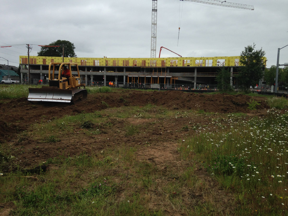
Breaking ground, moving dirt!
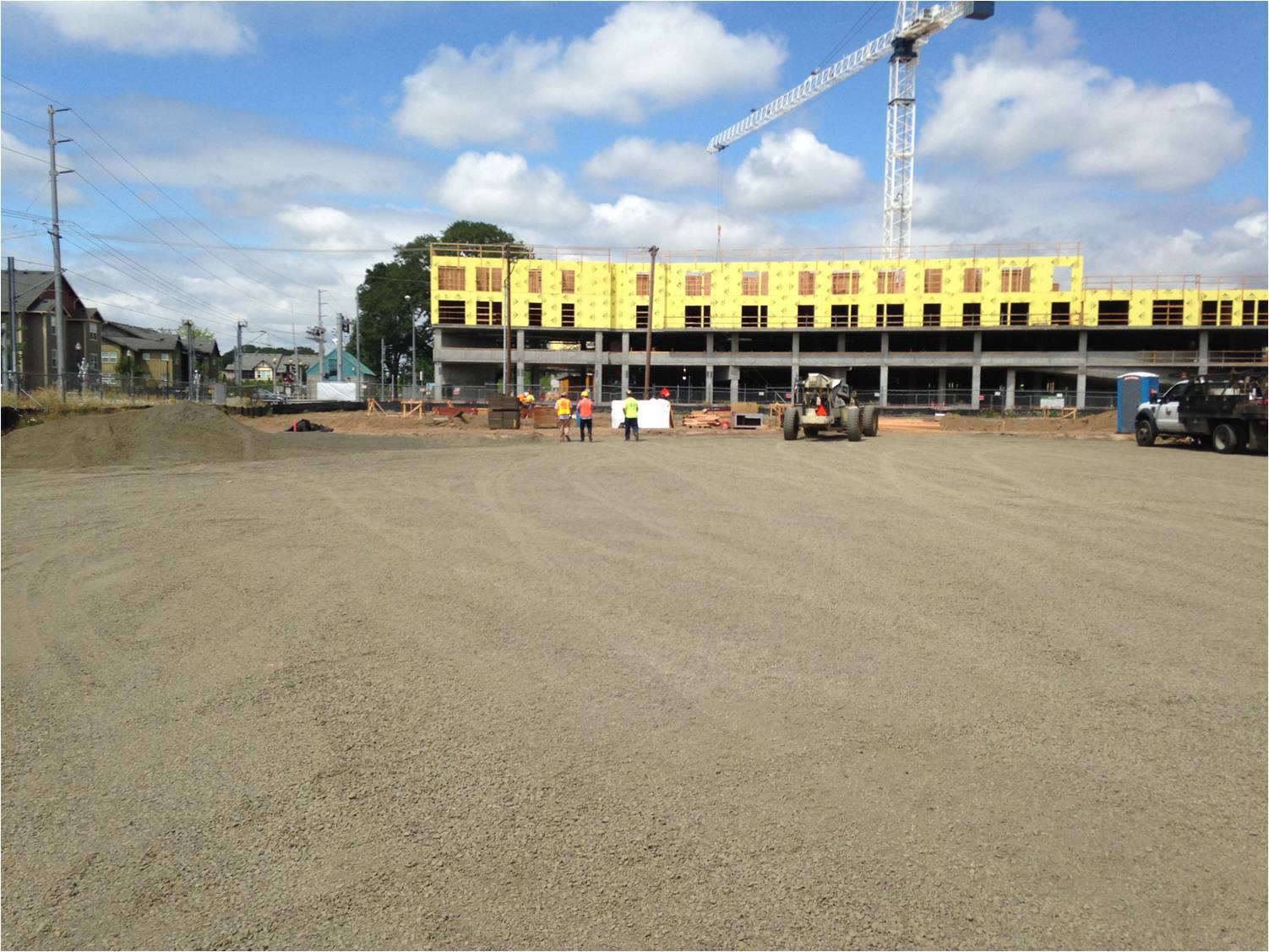
The site has been cleared and a rock pad placed to accommodate construction traffic. The building visible in the distance (to the west of our site) will be a mixed-use, market rate apartment building when completed in 2015.
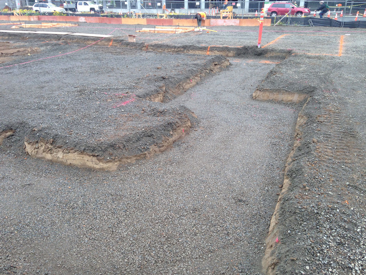
Initial excavations for footings at the building perimeter. Note the use of compacted gravel to establish a firm and level base for the foam insulation that is placed under the footings. The design documents called for controlled density fill (CDF) at locations where needed; however, the excavation contractor did an excellent job with the subgrade and gravel base preparation and after quality control inspections it was agreed that the CDF was not needed.
As clearing and grubbing began at the site, and then the initial excavation activities, the construction team began a detailed coordination process. To properly construct a high performance passive house design, diligent, proactive coordination of the work is required of the general contractor. There is no substitute for diligence when it comes to this coordination. Even a highly developed and accurate set of design documents does not include all the information needed to build the project, and inevitably there will be some gaps in documentation or a need to modify a detail slightly, or in a major way, to achieve the design intent while accommodating construction variables such as sequencing of the work, manufacturer’s installation instructions, etc.
Coordination of the work is fundamental to all construction projects but the need is heightened when executing a passive house design, especially when it comes to the detailing of the airtight and thermal bridge-free building envelope. For example, at some detail conditions there could be four or more trades that impact the air tightness of the building since they each supply and/or install components that are integral to the air barrier system. An important duty of the general contractor is to actively communicate with the entire group of subcontractors, to let them know about the passive house goals
and requirements on the project, and to educate them about key issues that may impact their scopes of work and the overall passive house certification. Due to the intricacies involved with material specifications and detailing of the passive house design, communication with the subcontractors that impact the building envelope needs extra attention. On the Orchards project, a full day Building Envelope Coordination (BEC) meeting was held on site during the first month of construction, to gather together all the envelope-related subcontractors and key suppliers and review project requirements, including specifications, detailing, schedule, sequence of trades, etc. Scheduling this meeting very early during construction allowed the team to work through any gaps or inconsistencies in the scopes of work of various trades, as well as any issues related to the design documents. Upon completion of the BEC meeting, resolved issues were addressed readily and efficiently through the project submittal process. Issues that needed further examination or design work were addressed through the project Request for Information (RFI) process. The coordination work touched all major elements of the design, including the foundation, exterior walls, windows and doors, and the roof.
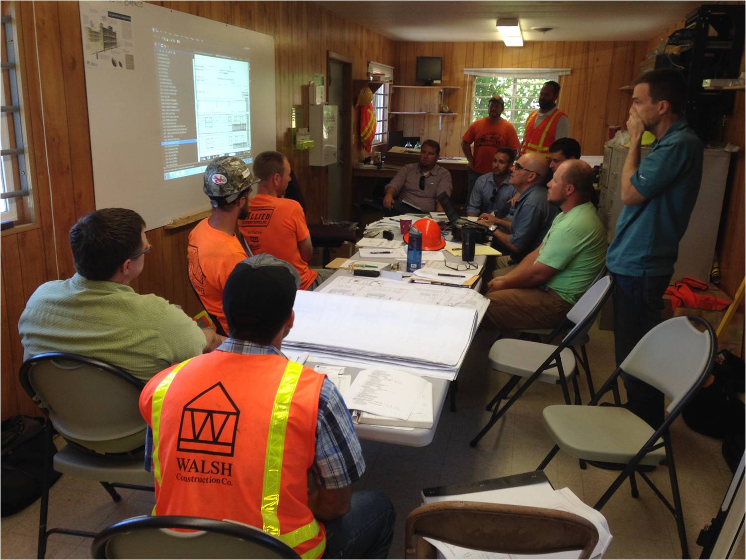
WALSH project teams convene a comprehensive Building Envelope Coordination (BEC) meeting on all projects early in the construction phase. The need for the meeting on the Orchards project was even more critical than it is typically, given the importance of envelope performance to achieving the Passive House standard. Here the team can be seen reviewing critical envelope details with the siding subcontractor. The architect and owner’s representative are present to help with interpreting project requirements and to participate actively in dialogue with the people who will be implementing the design in the field. This dialogue is vital in terms of verifying the design requirements and also for identifying questions about the design intent, conflicts in the design information, or possible omissions. By holding this session very early during the construction phase, the team can proactively work to resolve questions or other issues well ahead of when the work will be performed.
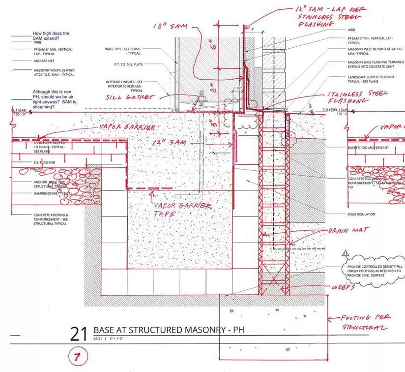
Example of coordination drawings developed by WALSH after the BEC meeting, to clarify design intent and coordinate the work of multiple trades. These drawings were issued to the architect as a Request for Information to facilitate clarification of the requirements and document approval by the architect. Note the revised location of the vapor barrier and the termination detailing for the vapor barrier shown in these drawings. The vapor barrier had been indicated below the slab insulation in the architect’s assembly drawing and had not been indicated in the footing details. A proactive coordination process resulted in relocating the vapor barrier above the slab insulation and clarified the vapor barrier termination requirements. Note also the dimensional coordination of the self-adhered membrane (SAM) strips used in sequence and configuration to serve as flashing for watertightness – and also to achieve sealing for airtightness – at the base of wall conditions. The submittal process (including shop drawings) is another vehicle used to clarify requirements and obtain approval of any required adjustments to the design.
An important concern that arose during the coordination process was the location and detailing of the sub-slab vapor barrier. The vapor barrier was not clearly indicated in the architect’s details, although a vapor barrier had been specified. In the slab on grade assembly drawing, the vapor barrier was indicated to be installed below the slab insulation. The Walsh team questioned this location, given our concern that a large amount of water could collect in the slab insulation layer if it should rain prior to a slab pour. The configuration of insulation and vapor barrier essentially created a sealed “bathtub” that could hold a lot of water. Not a good scenario! Even though we were in the dry summer months in Portland, there is always a chance of rain. When we pointed this out, the architect understood the concern and agreed with relocating the vapor barrier to the top of the slab insulation. Furthermore, the detailing of the vapor barrier at the foundation perimeter was not clear in the design drawings. We discussed this with the architect and sorted out the termination details as part of the coordination process, working with the vapor barrier manufacturer’s standard details and sealing products. With these details resolved, construction on the building foundation began.

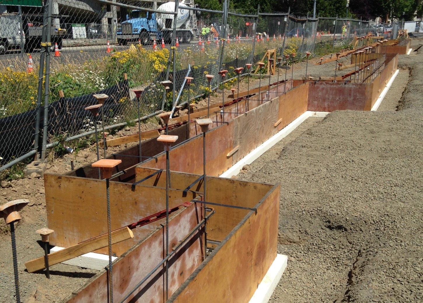
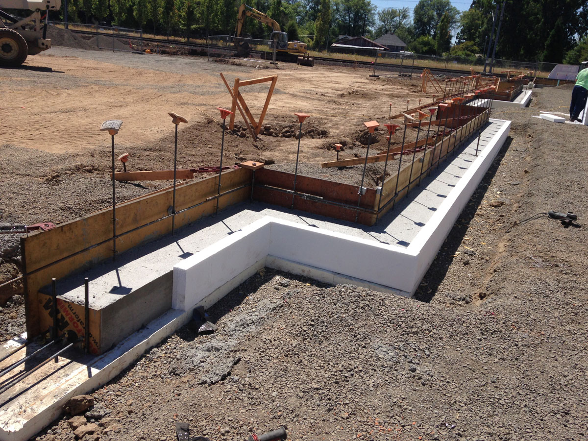
The building edge is laid out on the compacted and level gravel base installed over the subgrade, foam is placed, and work begins on the formwork for the perimeter footings.
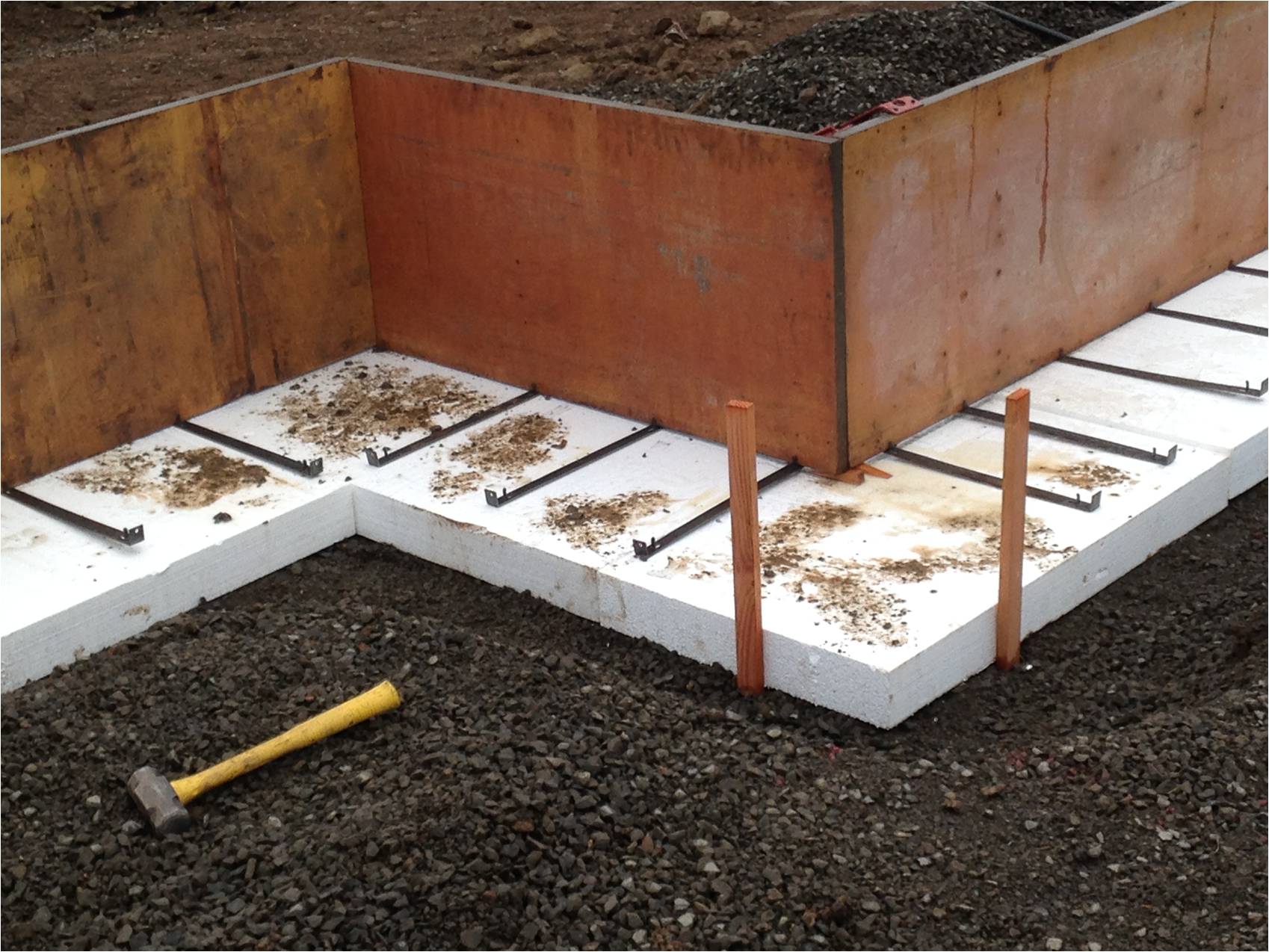
The foam sits firmly on the gravel base. Due to the excellent work by the excavation subcontractor, controlled density fill was not required.
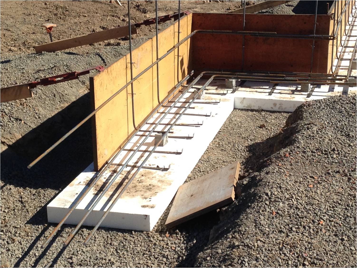
Footing formwork in progress.
Detail view of foam insulation placed on gravel base prior to completion of the footing formwork. Note the tight joints and the firm placement on the compacted gravel base.
View of footing work in progress. Interior formwork has been stripped and foam is placed on the interior face of the footings.
Link to the PDF file.